PCI Express Max Read Request, Max Payload Size and why you care
本文转载自:PCI Express Max Read Request, Max Payload Size and why you care
Modern high performance server is nearly all based on PCIE architecture and technologies derived from it such as Direct Media Interface (DMI) or Quick Path Interconnect (QPI).
For example below is a sample block diagram for a dual processor system:
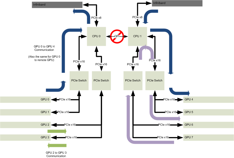
A PCI Express system consists of many components, most important of which to us are:
- CPU
- Root Complex (Root Port)
- PCIE Switch
- End Point
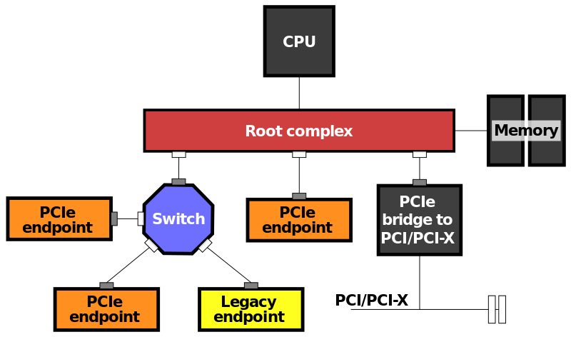
Root Complex acts as the agent which helps with:
- Receive CPU request to initiate Memory/IO read/write towards end point
- Receive End Point read/write request and either pass it to another end point or access system memory on their behalf
The End point is usually of most interest to us because that’s where we put our high performance device.
It is GPU in the sample block diagram while in real time it can be a high speed Ethernet card or data collecting/processing card, or an infiniband card talking to some storage device in a large data center.
Below is a refined block diagram that amplify the interconnection of those components:
Based on this topology let’s talk about a typical scenario where Remote Direct Memory Access (RDMA) is used to allow a end point PCIE device to write directly to a pre-allocated system memory whenever data arrives, which offload to the maximum any involvements of CPU.
So the device will initiate a write request with data and send it along hoping root complex will help it get the data into system memory.
PCIE, different from traditional PCI or PCI-X, bases its communication traffic on the concepts of packets flying over point-to-point serial link, which is sometimes why people mention PCIE as a sort of tiny network topology.
So the RDMA device, acting as requester, sends its request package bearing the data along the link towards root complex.
The packet will arrive at intermediary PCIE switch and forward to root complex and root complex will diligently move data in the payload to system memory through its private memory controller.
Of course we would expect some overhead besides pure data payload and here goes the packet structure of PICE gen3:
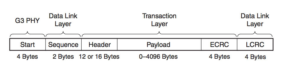
So obviously given those additional “tax” you have to pay you would hope that you can put as large a payload as you can which would hopefully increase the effective utilization ratio.
However it does not always work and here comes to our discussion about “max payload size”.
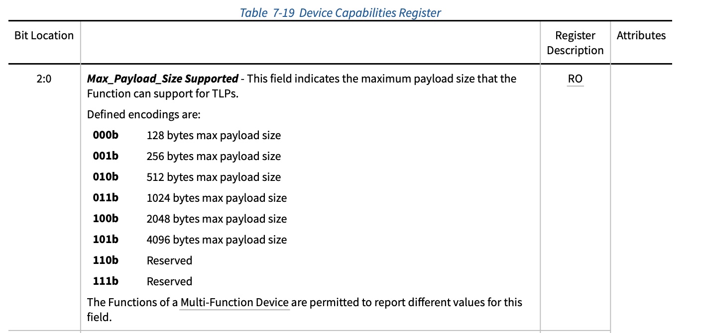
Each device has a “max payload size supported” in its dev cap config register part indicating its capability and a “max payload size” in its dev control register part which will be programmed with actual “max playload set” it can use.
Below shows the related registers extracted from pcie base spec:
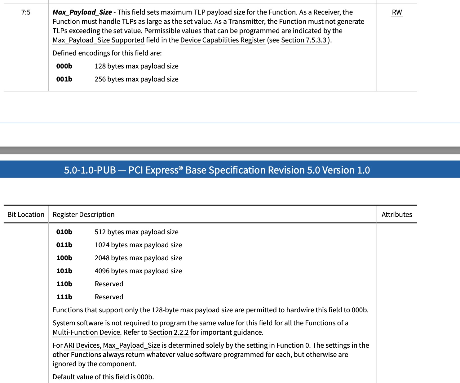
So how do we decide on what value to set within the range not above max payload supported?
The idea is it has to be equal to the minimum max payload supported along the route.
So for our data write request it would have to consider end point’s max payload supported as well as pcie switch (which is abstracted as pcie device while we do enumeration) and root complex’s root port (which is also abstracted as a device).
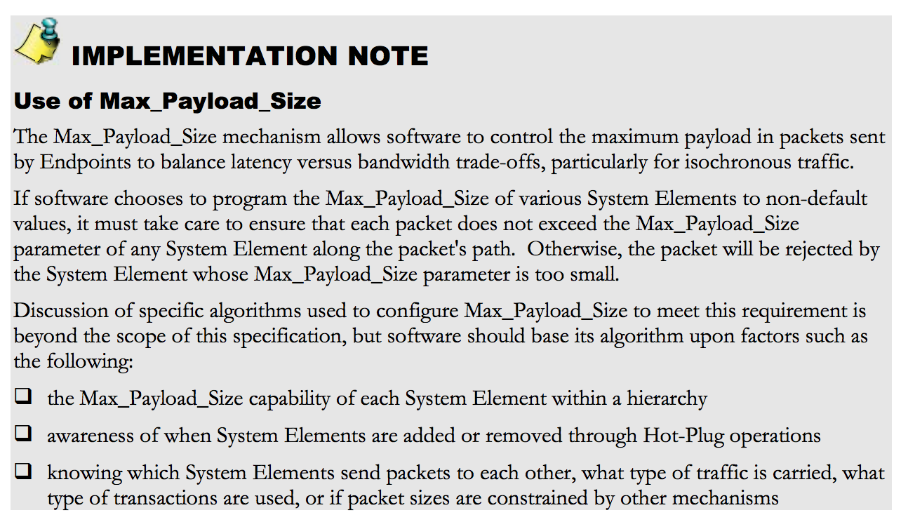
PCIE base spec actually described it this way without giving detailed implementation:
Now let’s take a look at how linux does it.
1 | static void pcie_write_mps(struct pci_dev *dev, int mps) |
So linux follows the same idea and take the minimum of upstream device capability and downstream pci device.
The only exception is for root port which is supposed to be the top of PCI hierarchy so we can simply set by its max supported.
pcie_set_mps does real setting of the config register and it can be seen that it is taking the min.
Now we have finished talking about max payload size, let’s turn our attention to max read request size.
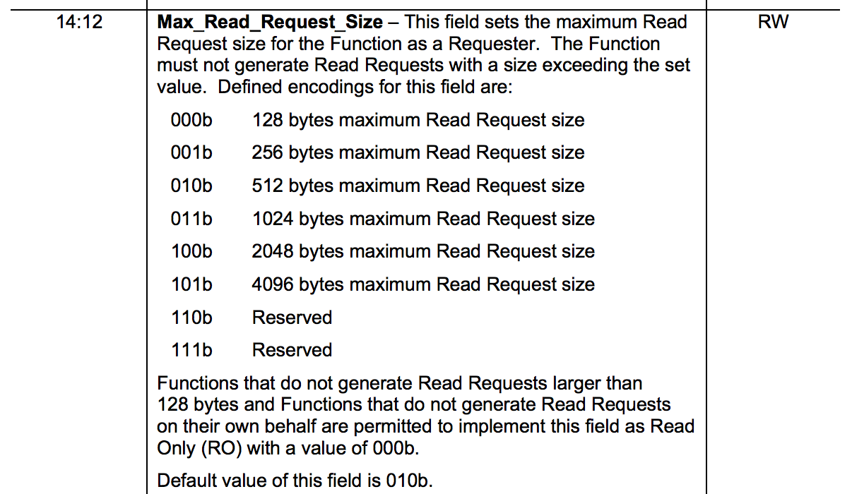
It does not apply to memory write request but it applies to memory read request by that you cannot request more than that size in a single memory request.
We can imagine a slightly different use case where some application prepares a block of data to be processed by the end point device and then we notifying the device of the memory address of size and ask the device to take over.
The device will have to initiate a series of memory read request to fetch the data and process in place on the card and put the result int some preset location.
So even though packet payload can go at max to 4096 bytes the device will have to work in trickle like way if we program its max read request to be a very small value.
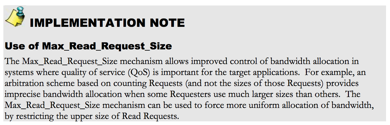
Here is the explanation from PCIE base spec on max read request:
So again let’s say how linux programs max read request size:
1 | static void pcie_write_mrrs(struct pci_dev *dev) |
pcie_set_readrq does the real setting and surprisingly it uses max payload size as the ceiling even though it has not relationship with that.
We can well send a large read request but when data is returned from root complex it will be split into many small packets each with payload size less or equal to max payload size.
So above code is mainly executed in PCI bus enumeration phase.
And if we grep with this function name pcie_set_readrq we can see other device drivers provide overrides probably to increase the read request efficiency.
So how big an impact the two settings has on your specific device?
It’s hard to tell though you can easily find on the internet discussions talking about it.
Here is a good one Understanding Performance of PCI Express Systems.
And here is another good one PCI Express Max Payload size and its impact on Bandwidth.